Work Experience

Apple

Firmware QA Engineer
Cupertino, CA
July 2016 - present

Apple

Hardware Engineering Intern
Cupertino, CA
May 2015 - August 2015

John Deere & Company

Information Technology Intern
Moline, IL
May 2014 - August 2014

  • Redesigned the user interface of a high-visibility company application toolset to drastically increase usability and productivity
  • Translated team requirements and user feedback to develop time-saving web applications automating several processes
  • Worked extensively with HTML, CSS, JavaScript, SQL, and VB.NET
  • Abbott Laboratories

    Business Process Systems Intern
    Abbott Park, IL
    May 2013 - August 2013

  • Assisted in financial data system reorganization following a company split
  • Managed and organized resolution of “out of tolerance” purchase orders
  • Assisted in cleanup and maintenance of Contract Lifecycle Management system, Total Supplier Management System, and other various SAP applications
  • Baxter Credit Union

    Information Systems Intern
    Vernon Hills, IL
    January 2011 - August 2012

  • Created and performed automated testing of online banking sites, saving hundreds of employee hours monthly
  • Worked with employees to create a new request and mapping system for testing environments using SQL and Access databases
  • Assisted in reorganization of company electronic file system
  • Education

    B.S.E. Computer Engineering

    University of Michigan Class of 2016


    Hardware Courses

  • ENGR 100 - Underwater Vehicle Design
  • EECS 215 - Intro to Electronic Circuits
  • EECS 216 - Intro to Signals & Systems
  • EECS 270 - Intro to Logic Design
  • EECS 370 - Intro to Computer Organization
  • EECS 373 - Design of Microprocessor Based Systems
  • EECS 461 - Embedded Control Systems
  • EECS 473 - Advanced Embedded Systems

  • Software Courses

  • ENGR 101 - Intro to Computers & Programming
  • EECS 203 - Discrete Mathematics
  • EECS 280 - Programming & Data Structures
  • EECS 281 - Data Structures & Algorithms
  • EECS 482 - Intro to Operating Systems
  • EECS 485 - Web Databases & Info Systems
  • Projects

    Sound Activated LEDGrid

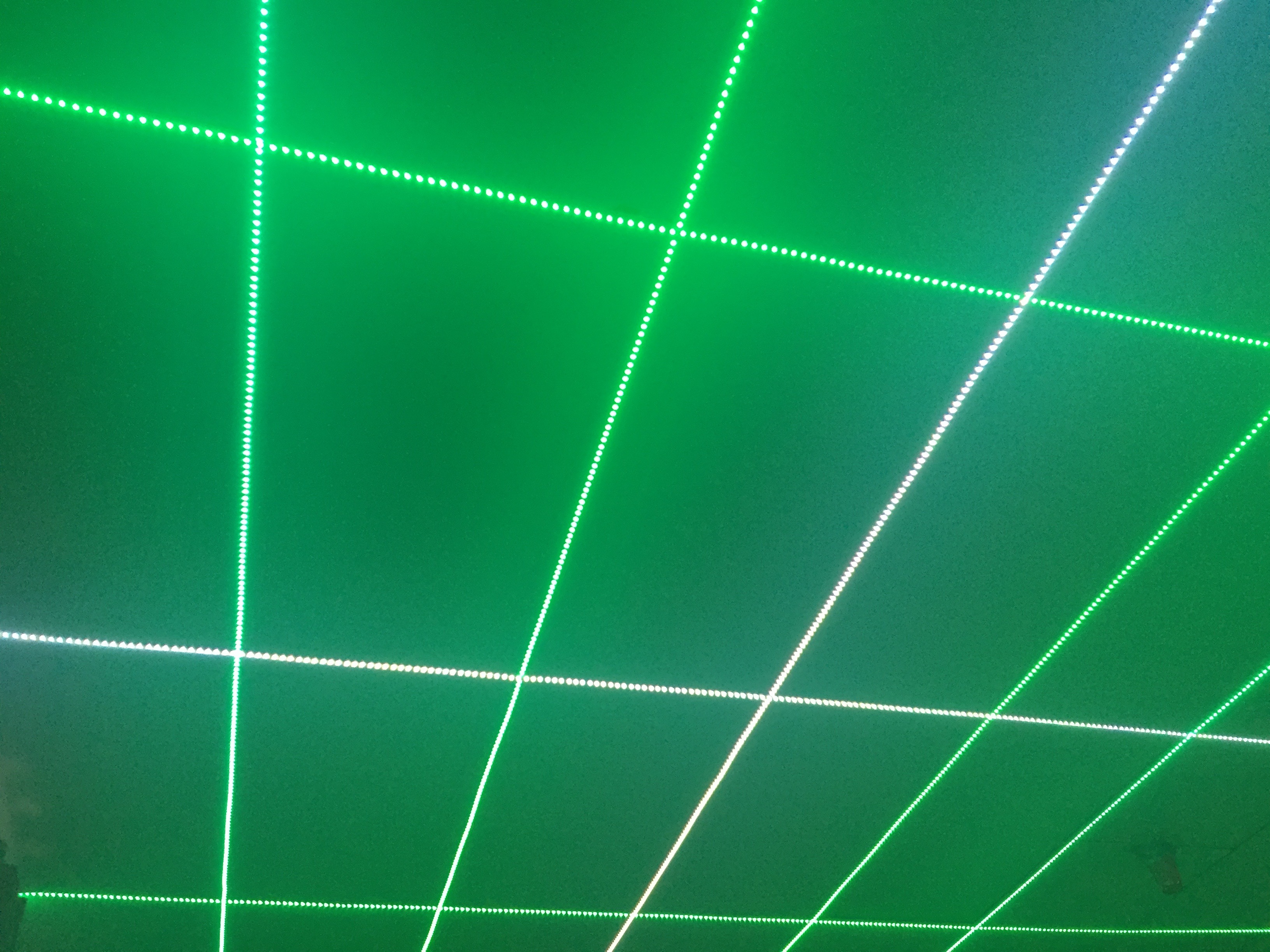
    This is one of the most fun and satisfying personal projects I have worked on. I used the LEDGrid as the main source of lighting in my room. It is completely customizable in color and brightness, controlled by my Automation Control Center project. I was also able to animate the grid based on the music being played from my computer. To see a basic video of it in action, click here!

  • The LEDs - some cheap 5 meter long, analog LED strips with 300 LEDs/meter stuck with double sided tape to my drop-ceiling support beams.
  • The Wiring - long CAT5 cables soldered to the LED wiring ran through my drop-ceiling and down behind a support beam near my desk into the control box.
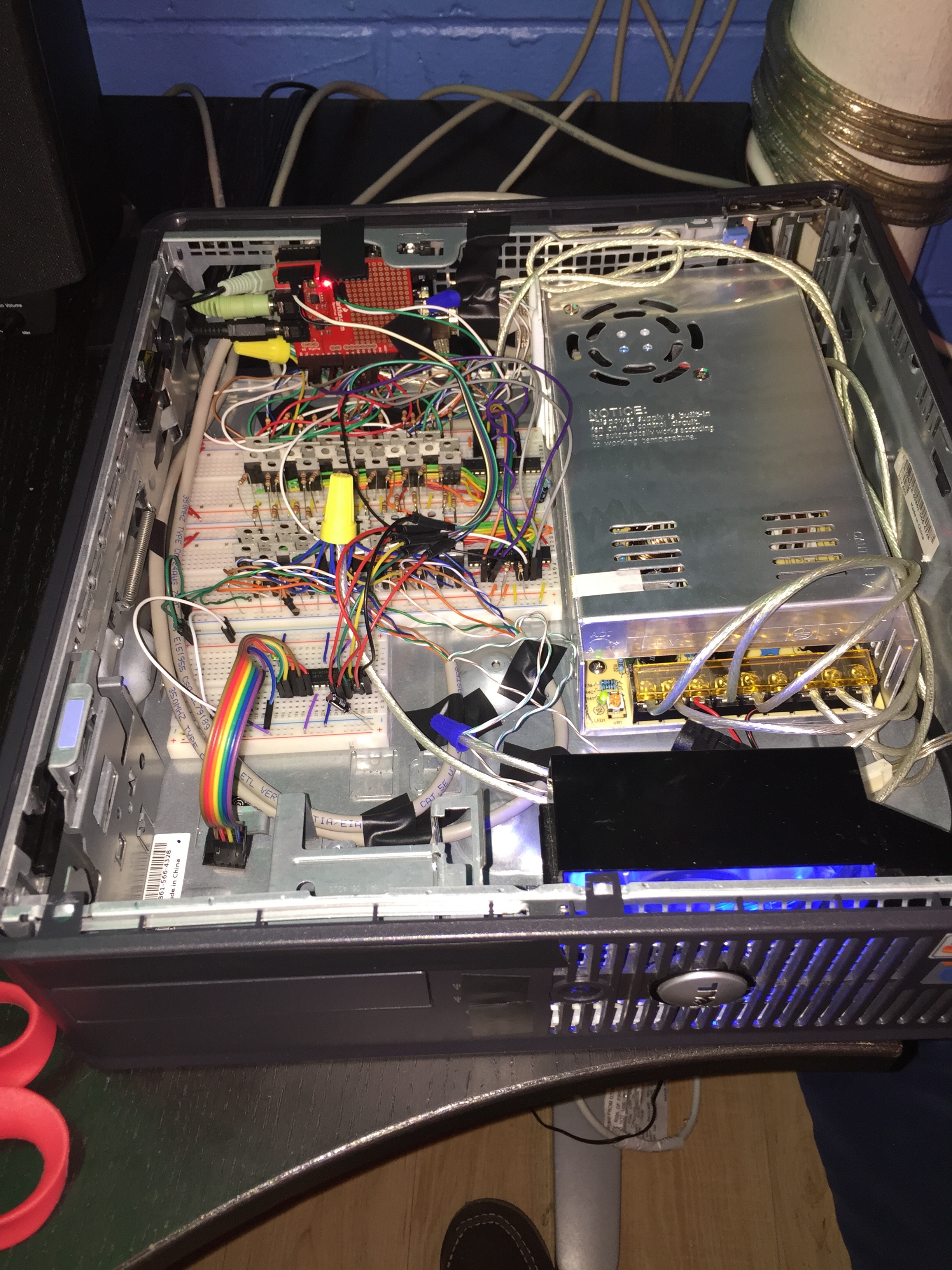
  • The Enclosure/Power - an old slim Dell PC case with all the components removed and retrofitted with a 12-volt dedicated power supply to power all 2400 LEDs, as well as an 80mm fan to keep the case cool.
  • The Microcontroller - an Arduino Uno with an attached Spectrum Shield that is connected between my computer audio output and my speakers as a passthrough to grab audio data used for animating the grid.
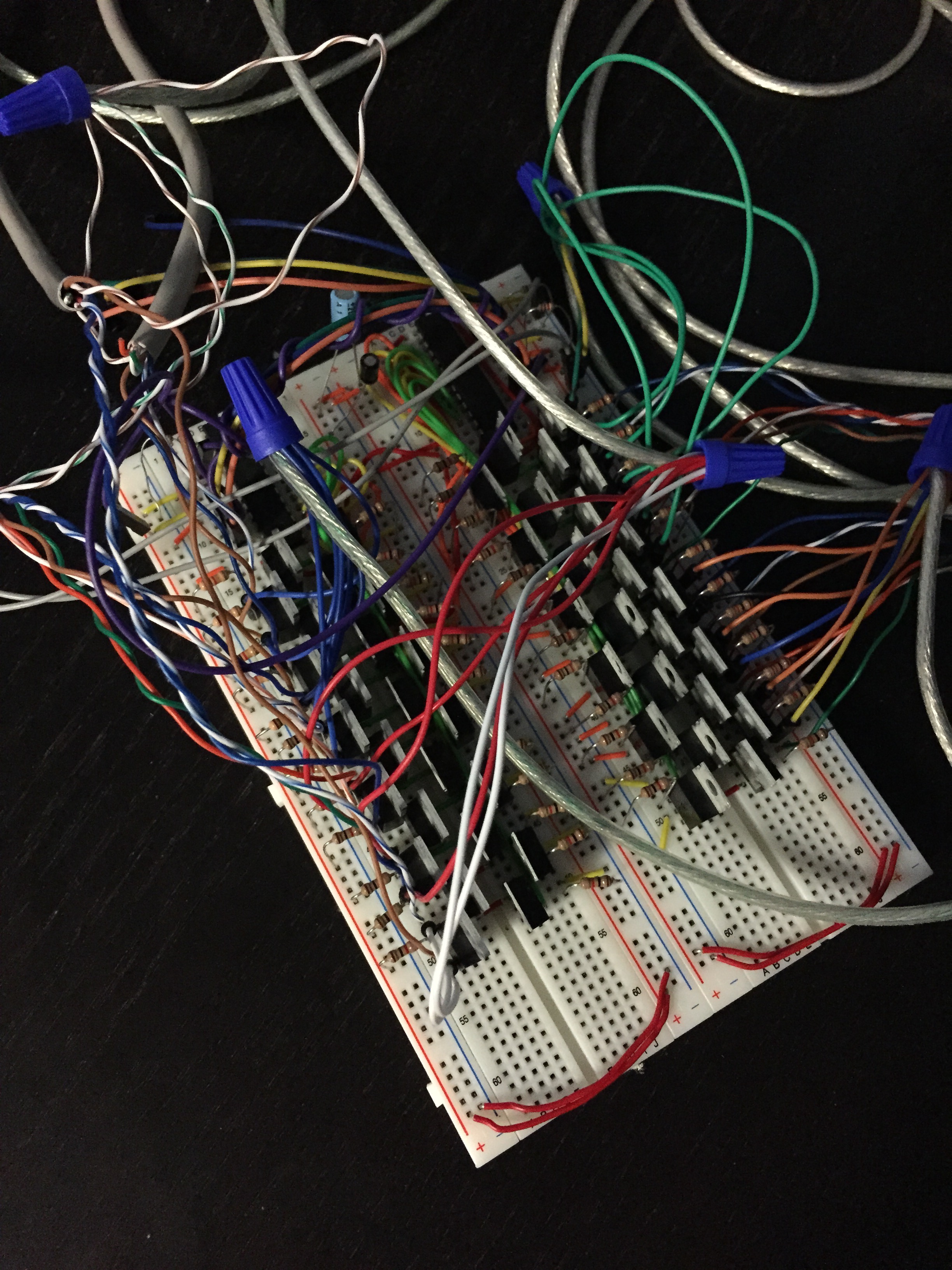
  • The Control Circuitry - since the Arduino has a limited number of outputs (and I had 24 channels worth of LEDs), I used two TLC5940 chips to add more PWM outputs using a serial bus. Each channel fed into a transistor that switched an N-Channel MOSFET to control the LEDs. The MOSFETs were required due to the large amount of power used by the LEDs (up to 1 amp per channel @ 12 volts). I also used an ATMega328 with connected 2.4GHz RF transceiver to receive signals from my Automation Control Center and transmit them to the main Arduino (for remote mode control).
  • Home Automation Outlets

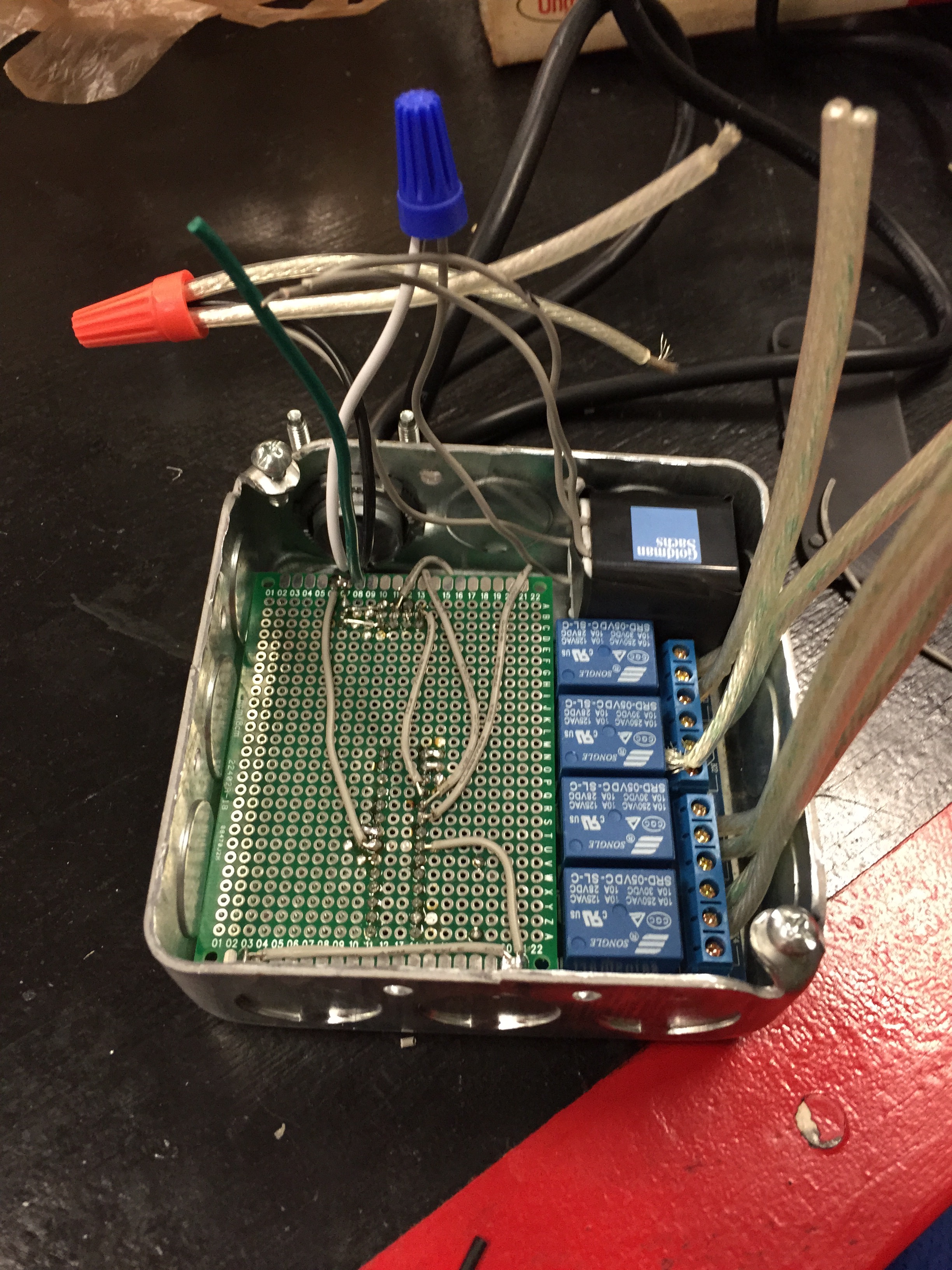
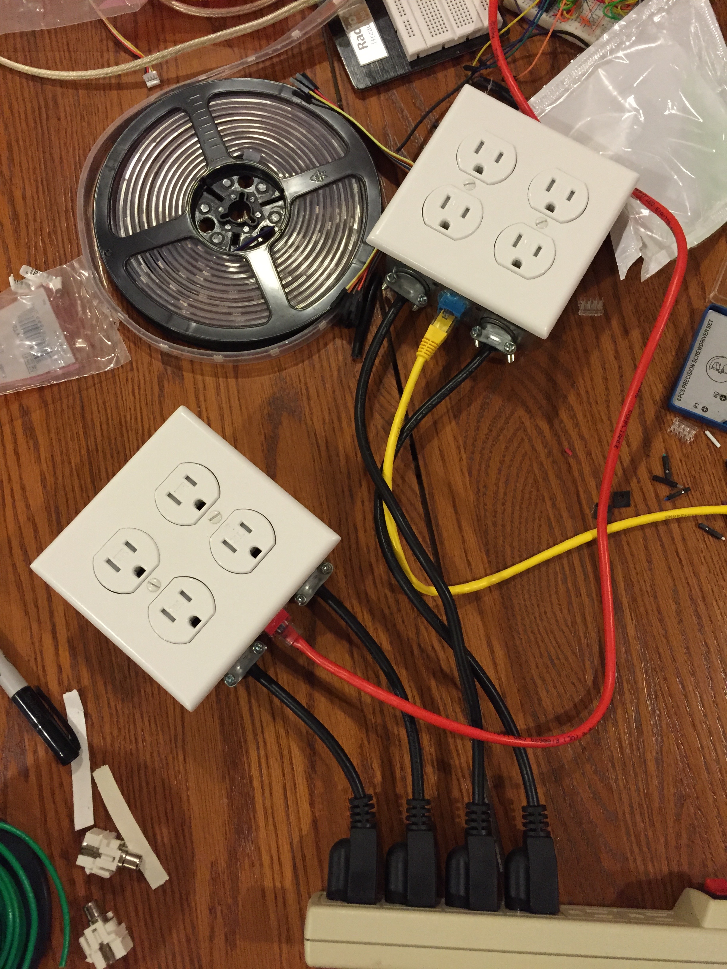
    Another piece of the puzzle in automating my room, I created these outlet boxes to allow me to control my lights and appliances. Originally, I had relay modules wired between short extension cords cut in half to turn things on and off with an Arduino, but in an effort to make it look a bit nicer (as well as decreasing risk of electrical shock/fire), I decided to squeeze all the components into a box. For the first iteration of these boxes, I ran signal wires from the Arduino sitting at my desk with CAT5 (seen in the picture below on the right), but I later upgraded the boxes to be controlled using RF signals received from my Automation Control Center. Each of the four outlets on each box could be individually toggled on or off via wireless RF signal, and I used the boxes to automate my desk lamp, room accent lighting, computer monitors, and speakers. Click here to see a video of me using these outlet boxes to have a little fun with Christmas lights!

  • The Outlets/Enclosure - went on a quick Home Depot run and acquired a few tamper-resistant outlets, a couple outlet boxes (made to be mounted in-wall but work well enough for my purposes), as well as a couple risers for the boxes and wall-plates for the outlets.
  • The Microcontroller - because the case was so small, I couldn't fit an entire Arduino board inside, so I bought a couple prototyping PCBs and soldered all of my components to it. I used an ATMega328 sitting on an IC socket as the brains, powered by a cheap USB wall-wart AC adapter run through a 5V voltage regulator. This was connected to a 2.4GHz RF transceiver to receive signals from my Automation Control Center, as well as a 4-channel relay module to switch power to the outlets.
  • The Wiring - I took an old 3-prong computer power cable, cut off the end, and ran the wires into the outlet box (with a clamp to hold it in). I used some 16 AWG wire and wire-nuts to run the "hot" (black) and ground (green) wires to each outlet, and then ran the neutral (white) wires through the relay module to the outlet so each plug could be individually switched. I also ran wires to the USB wall-wart AC adapter to power the microcontroller.
  • Automation Control Center

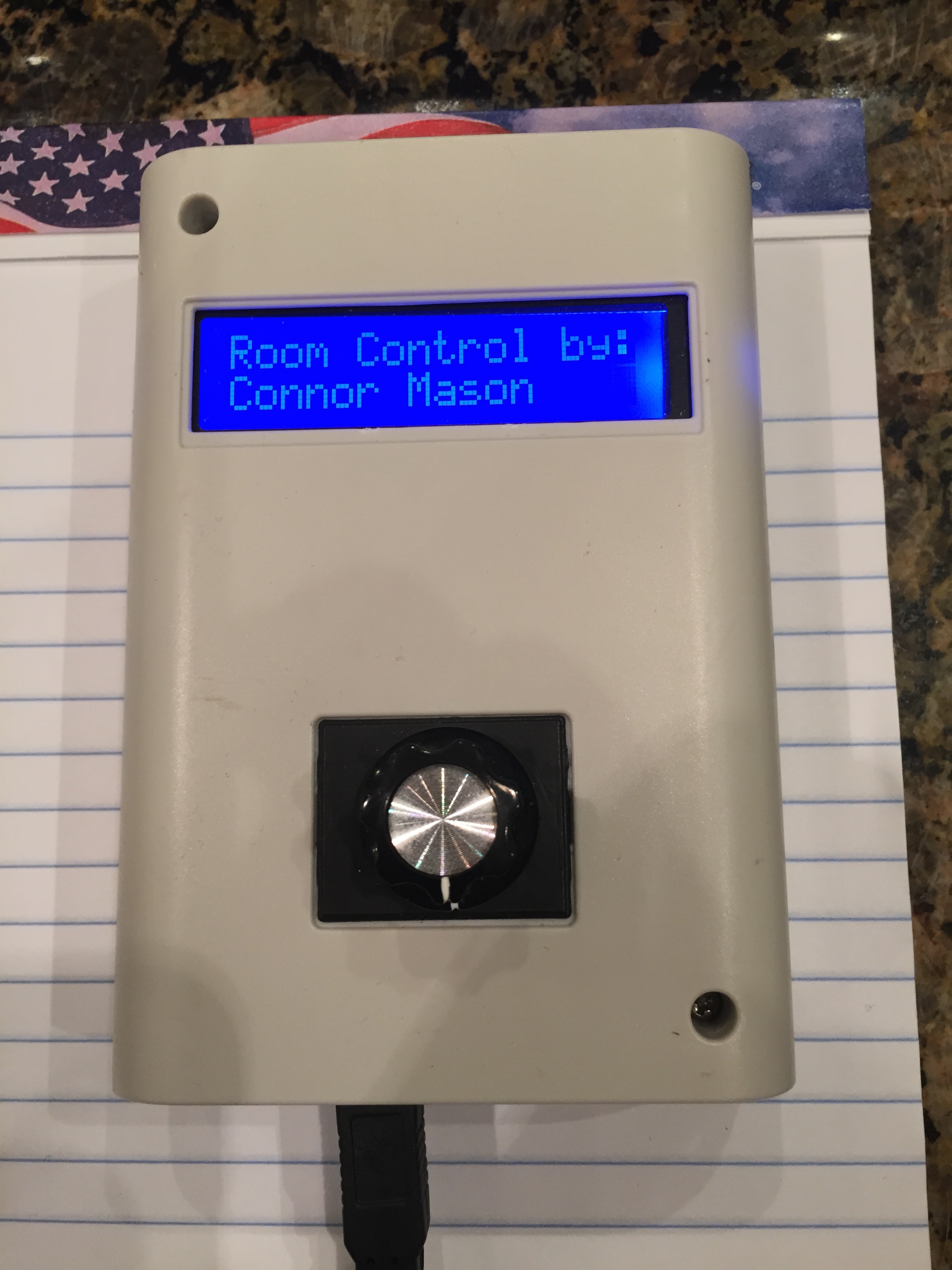
    The main control center that ties both of the above projects together. My vision for everything was to completely automate all the lighting and appliances in my room, and that is what this control center allows me to do. Using the LEDGrid (above) as my main source of lighting in the room, and the Home Automation Outlets to turn everything else on and off, I am able to control almost everything I want to using just this small device mounted by my door like a lightswitch. It allows me to choose between different "modes", and will somewhat intelligently guess what mode I want before touching it. Walking in the room? Use the normal lighting mode to make the LEDGrid a warm shade of white for lighting. Study time? Use the study mode to change the LEDGrid to a brighter white to keep me more awake, as well as turning on my desk lamp. Trying to throw a party? Hit party mode to make the LEDGrid move to the beat of the music, turn on the blacklights, and start up my speakers.

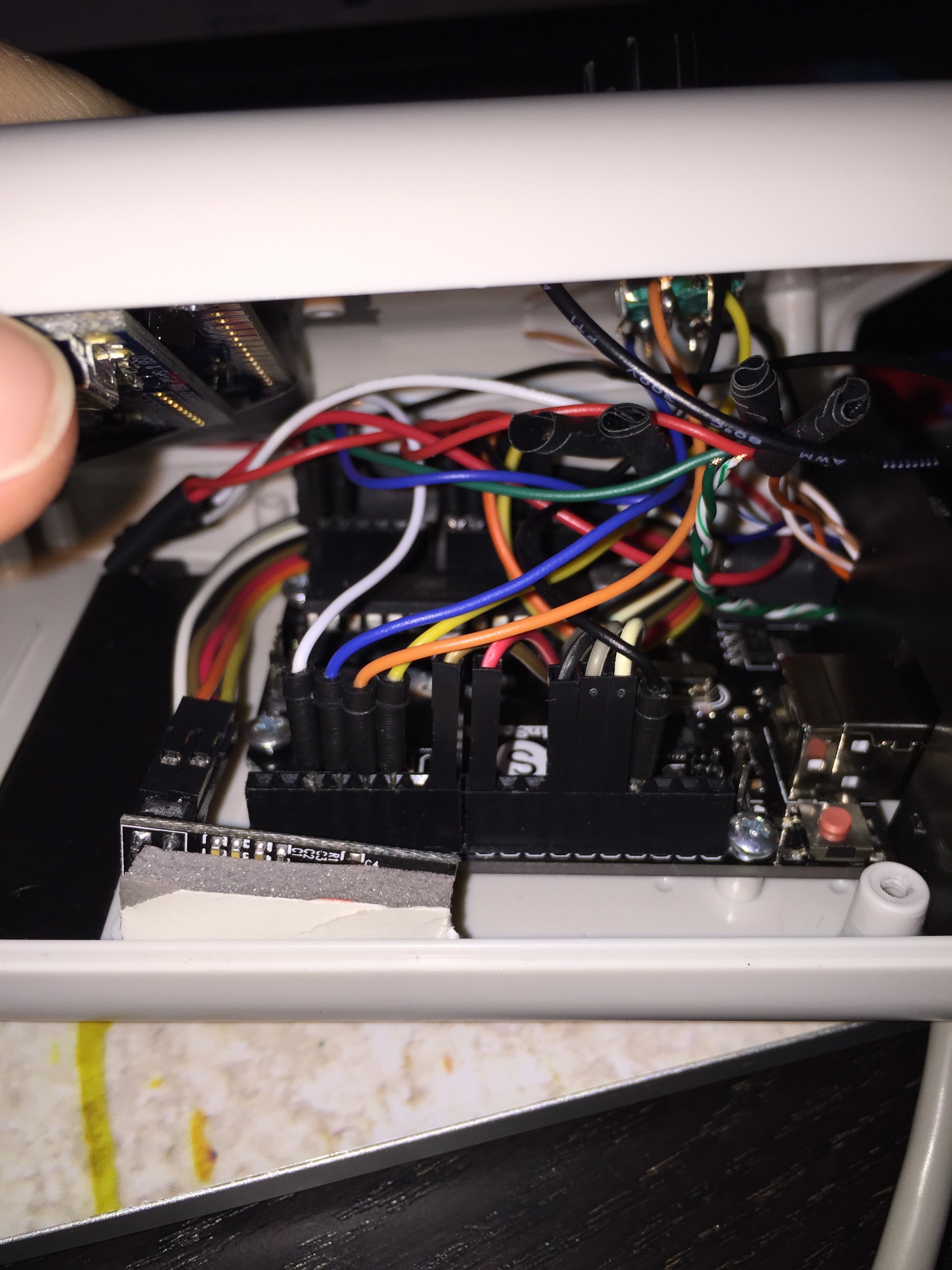
  • The Enclosure - a small plastic case capable of holding an Arduino Uno and an LCD.
  • The Microcontroller - the basic Arduino Uno plugged into a standard USB wall-wart AC adapter.
  • The I/O Devices - mounted inside the enclosure I had an RGB backlit LCD display with serial backpack wired to the internal Arduino, as well as a rotary encoder with a knob mounted in the middle for mode selection. There was also a 2.4GHz RF transceiver mounted/wired inside the case so that the control center could talk to my LEDGrid and Home Automation Outlets.
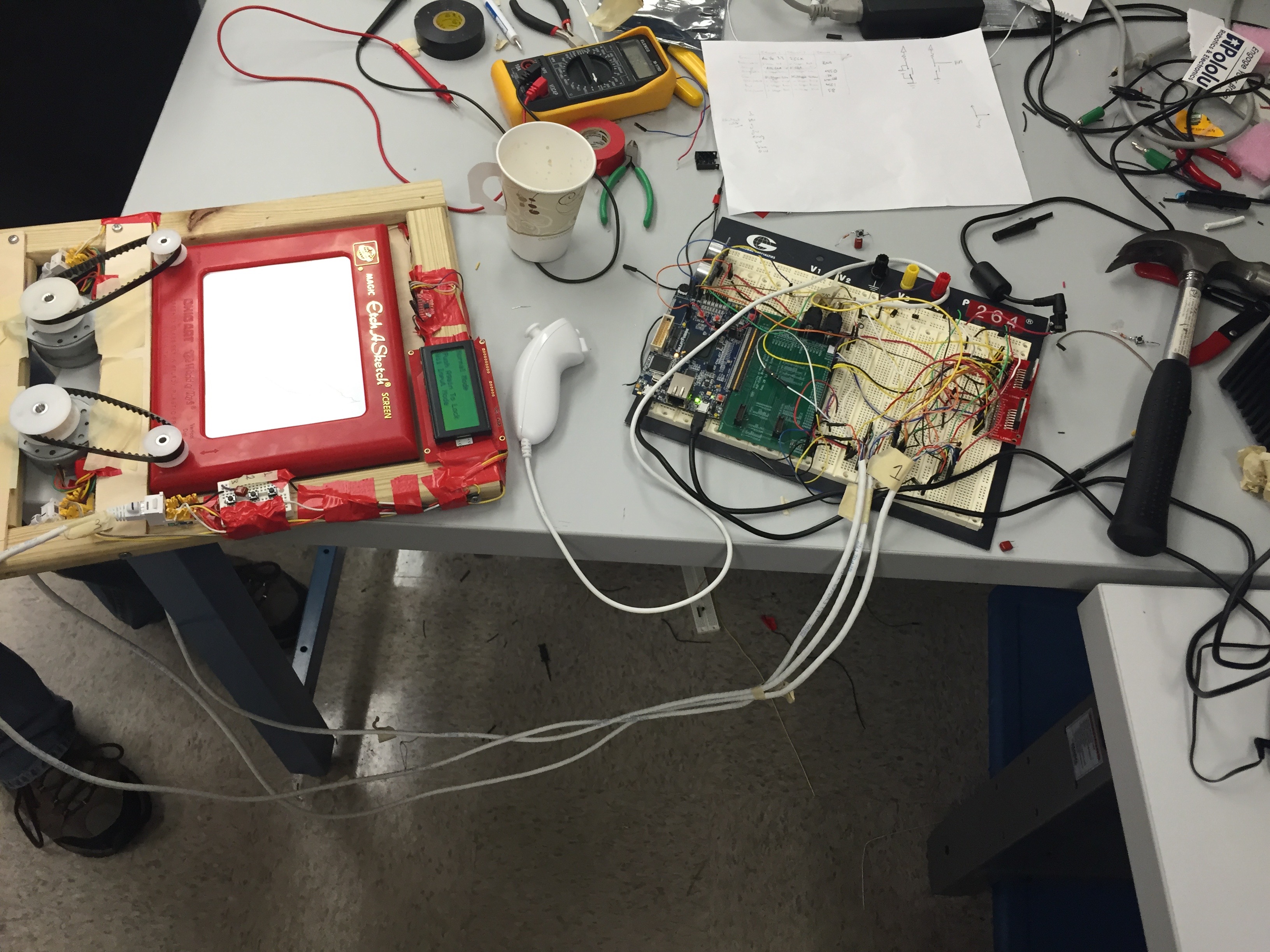
  • Etch-A-Sketch 2.0

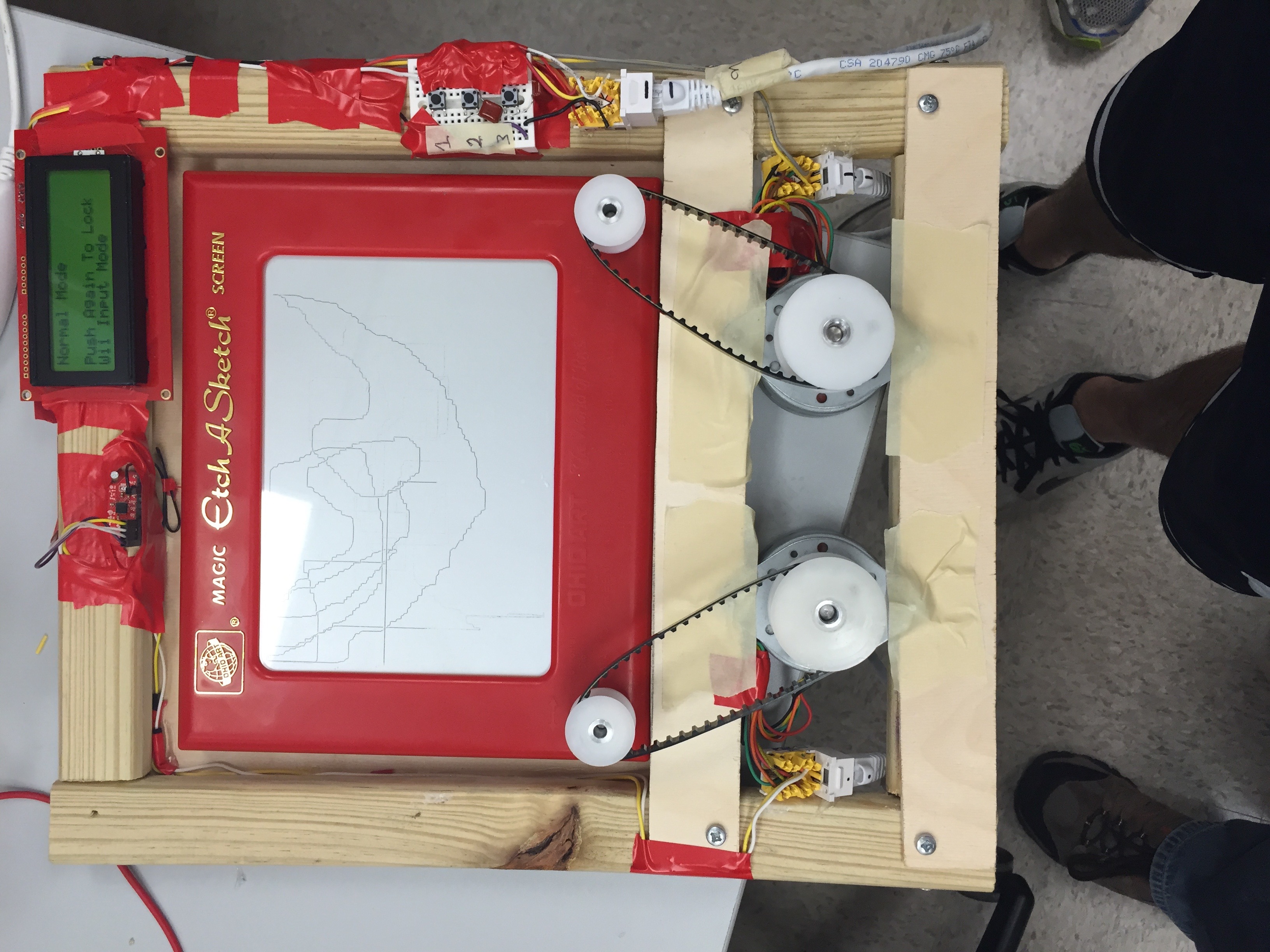
    A fun class final project for EECS373 (Design of Microprocessor Based Systems). We created a makeshift enclosure you could set a normal Etch-A-Sketch into that would allow you to control by either tilting the enclosure in any direction (via accelerometer) or by using a Wii Nunchuck controller. We had a few "game"-like features, such as timed draw mode, and the ability to record what you drew and have the system redraw it for you.

  • The Controller - a Microsemi SmartFusion development board with an FPGA and ARM Cortex M3. The entire project was coded in Verilog and C.
  • The Motors - two large stepper motors (one for each knob on the Etch-A-Sketch), wired with 12 volts through two stepper motor controllers.
  • The I/O Devices - we had the option of either using the Wii Nunchuck to control the device, or using an accelerometer/gyro connected via I2C bus. We also had 3 buttons and a UART LCD screen mounted on the frame.
  • The Wiring - most of the wiring was done on a breadboard, with all sensors, buttons, and motors attached to the breadboard using ethernet cables (so the device could easily be detached from the control board).